
US Army Characterized Continuous 3D Printed Carbon Fiber-Reinforced Thermoplastic Composite Parts11/30/2018
https://ift.tt/2E4kyUx
US Army Characterized Continuous 3D Printed Carbon Fiber-Reinforced Thermoplastic Composite Parts https://ift.tt/2DQnbZk 
Geometry of Tensile Specimens. A trio of researchers with the US Army Tank-Automotive Research Development, and Engineering Center (TARDEC) in Michigan recently published a study, titled “Characterization of Continuous Fiber-Reinforced Composite Materials Manufactured Via Fused Filament Fabrication,” that worked to characterize continuous carbon fiber-reinforced thermoplastic composite parts that were 3D printed on a Mark Two 3D printer.
As most 3D printed parts are built from the bottom up, it’s not unusual for out-of-plane material properties to be weaker than in-plane ones. When in-plane printing occurs of continuous fibers, the completed parts can have increased stiffness and in-plane strength, but researchers don’t have a clear idea as to how continuous fiber reinforcements affect an as-manufactured part’s mechanical anisotropy.
The researchers used the nylon-based thermoplastic Onyx by Markforged in their study, along with continuous carbon fiber tow coated with a binder material, and 3D printed several test specimens in order to gain a better understanding of how much of an influence the continuous carbon fiber reinforcement would be: • Group 1: Onyx (in plane, Nylon/Carbon plastic): ID# 1-1, 1-2, 1-3 To make analysis easier, the team only tested specimens with unidirectional fiber orientations. The pure Onyx specimens in the first group were 1.8 mm thick and used as a baseline, while the 0° specimens from Group 2 featured two 0.125 mm layers of Onyx on the roof and floor, along with two Onyx layers on the side walls; the rest was filled with carbon fiber that were “oriented longitudinally in the direction of pull for a tensile test.”

Schematic of specimens on print bed to show specimen placement and fiber orientation (where relevant). The Group 4 specimens were 3D printed vertically, and were tested for adhesion evaluation between fiber-reinforced layers. Then, the researchers conducted Thermogravimetric Analysis (TGA) and Fourier Transform Infrared (FTIR) Analysis on the Onyx specimens in order to gain a better understanding of the material’s thermal characteristics; tensile testing was also conducted until total specimen failure.
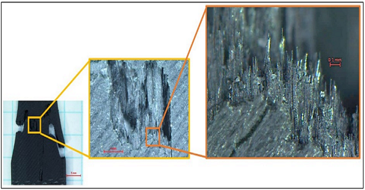
Detailed views of fracture surface of specimen 1-1, showing fiber breakage, fiber pullout, and matrix cracking. The researchers determined that the materials used in this study have a high degree of mechanical anisotropy, and that others need to consider the 3D anisotropic mechanical properties when they are used in structural applications. In addition, the team also determined that the traditional dog bone-shaped tensile bars they used for the study were not the best choice for specimens manufactured using CFF, mainly because of “the unique fiber placement process and local variations in fiber angle around the curved radii,” and recommend that other researchers use rectangular specimens with bonded tabs, per the ASTM D3039-17 Standard Test Method for Tensile Properties of Polymer Matrix Composite Materials. Co-authors of the paper are Robert J. Hart, PhD, Evan G. Patton, and Oleg Sapunkov. Discuss this research and other 3D printing topics at 3DPrintBoard.com or share your thoughts below. Printing via 3DPrint.com | The Voice of 3D Printing / Additive Manufacturing https://3dprint.com November 30, 2018 at 02:06AM
0 Comments
Leave a Reply. |
Categories
All
Archives
April 2023
|
 RSS Feed
